Calculation of Cv, Kv
Selecting the control valve for a given application depends on several factors, which are:
- Flow rate
- Pressure
- Temperature
- Corrosiveness or abrasion of a medium
- Requirements for tightness
- Application of specific industry norms (FDA, 3A, EPA…)
The capacity of a valve is given by the value of the flow rate coefficient, Cv or Kv, and shows the amount of water which flows through the valve under the defined conditions.
Cv – amount of water [U.S. gallon/min] when pressure drops 1 psi
Kv – amount of water [m3/h] when pressure drops 1 bar
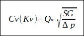
Q … volumetric flow rate, for calculation, Cv [U.S. gallon/min], for calculation, Kv [m3/h]
SG … specific weight (for water is SG=1)
Δp … pressure drop, for calculation, Cv [psi], for calculation, Kv [bar]
Simplified relationship between the coefficient Cv and Kv is:
Cv=1.15622 * Kv
Kv=0.86488 * Cv
The Calculation of the Flow Coefficient for Gases and Steam
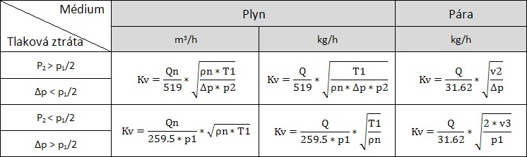
P1 [bar] Pressure upstream of the valve
P2 [bar] Downstream pressure
T1 [K] Temperature upstream of the valve (°C +273.16)
Δp [bar] Pressure drop across the valve (p1-p2)
Q [kg/h] Mass Flow Rate
Qn [m3/h] Volumetric flow rate of gas at standard conditions (T=0°C, P=1 bar)
ρn [kg/m3] Gas density at standard conditions (T=0°C, P=1 bar)
v2 [m3/kg] Specific volume of steam for p2 and T1
v3 [m3/kg] Specific volume of steam for p1/2 and T1
Technical Tables
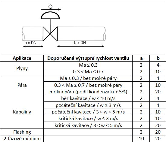
Recommended Output Velocity of the Valve and Length of the Input and Output Pipes
Flashing
The presence of flashing or cavitation in a valve can have a significant effect on its calculation and selection. Both phenomena can cause damage to the valve or continuing pipe, therefore the correct selection of its size, type and inner assemblies are very important. We can hereby eliminate undesirable consequences, which are usually accompanied by both phenomena.
The following picture shows a distribution of pressure across the valve.
In the case that the output pressure, p2, gets below the vapor pressure, pv, of the given liquid (owing to the increased speed at the throttling point), the formation of bubbles occurs. The more that the output pressure, p2, decreases below the vapor pressure, pv, the faster is the formation of bubbles. Up to this point the course of flashing and cavitation is the same.
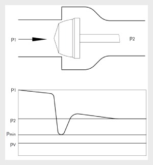
Distribution of Pressure in the Valve
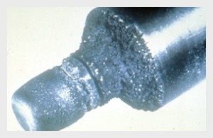
In the case of flashing, the value of the output pressure, p2, remains below the level of vapor pressure, pv, and bubbles are present at the output side of the valve. During flashing the valve is able to be damaged due to erosion. The following picture shows typical smooth, shiny cone damage from the occurrence of flashing.

Damage to the inner part of the valve (plug) from the influence of flashing– a shiny and smooth surface
When flashing occurs, we can only mitigate the consequences of damage and extend its lifetime by suitably chosen valve construction. An angle valve, with lining on the outlet, is the recommended construction during the occurrence of flashing.
Also, valves with reduced trim decrease the outlet velocity and thereby have consequences of producing damage to the valve due to the larger dimensions of the body. An important factor is making the right choice of hardened trim for a valve. An important factor is the right choice of hardened valve trim material and also suitable material of the valve body.
Cavitation
Cavitation occurs at the moment when the output pressure, p2, drops below the vapor pressure, pv, and then returns above that value again. At the moment when p2 increases above the pv value, it leads to a collapse (implosion) of the incurred bubbles. The collapse of bubbles releases energy and if they’re near a solid surface, leads to consequences of their gradual wear and tear, incurred by the effect of micro-jets and shock waves. The damage due to cavitation can be transmitted to the output pipe, where damage to other equipment can occur. Cavitation is accompanied by excessive noise, vibration and capacity constraints of the valve.
1) 1) A bubble which is moving into a higher pressure area.
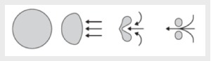
2) 2) The collapse of a bubble near a solid surface.
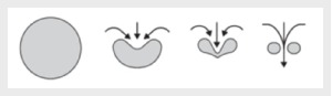
3) 3) A hemispherical bubble adhered to a solid surface.
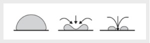
The basic measure which mitigates the consequences of valve damage due to cavitation is the usage of hardened materials in a high speed area (plug, seat). Regarding the selection method for the construction of a suitable valve, the application of cavitation index, Kc, is based on the standard recovery curve of pressure on the valve, which is preferred by many manufacturers. By using the cavitation index, Kc, pressure loss, (Δpc), is determined; at which time cavitation begins to show on the valve. The problem with the use of the cavitation index, Kc, is that it represents the cavitation, which only affects the capacity of the valve but not to the point where damage, noise and vibrations are generated. In regards to that fact, the issue of cavitation includes a wide range of variables (valve type, type of operation, etc.), we can claim that the calculation method and the universal cavitation index based on this method cannot cover all types of valves from various manufacturers. Therefore, a list of practical recommendations was published by the ISA society in 1995 (Recommended Practice), which includes the method for predicting damage due to cavitation for all kinds of valves. This method uses the sigma parameter, (σ), which is based on the measuring of collapsing bubbles of energy. It reflects the slope of the valve to cavitation and the beginning of possible damage.
P1 and p2 are the pressures in front of and behind the valve. Pv is a vapor pressure of liquid during a given operating temperature. Generally, the smaller the value of σ, the greater the slope is to the cavitation for a given application. The calculated value σ for a given process is compared with the value σ, which is allowed for the given valve. The allowed value σ for a valve is determined under the same process conditions. The allowed value σ for a type of valve is determined by tests listed in the ISA manual.
Damage to the inner part of the valve (plug) from the influence of cavitation – a dimpled surface
The best resistance to cavitation damage has globe (angle) valves equipped with a special multistage cage, where the number of stages is given by the size of pressure loss dp on the valve.
Noise formed by flow velocity or flow quantity
The largest number of noisy control valves we find on applications of pressure reduction on gases or on steam. The pressure loss on the valve is the cause of the release of energy, which is converted into heat, along with the remainder of the noise. Leaving aside the noise as a factor which negatively affects the environment, we have to take into account phenomena such as vibrations. Noises on valves create vibrations or on the contrary vibrations create noise. Vibrations may cause damage, not only to the valve itself, but very often lead to damage of the device arranged on the discharge pipe.
The easiest way to reduce the noise on the valve is the integration of suitable restrictions on the pipeline behind the valve. By this we increase the backpressure of a valve, i.e., we reduce the pressure loss and thus also the noise level. However, this method often works well only for one operating state but for other operating state is ineffective (the value of the flow coefficient restriction is constant).
The most common products offered for noise reduction on a valve are drilled cages. In the cage the flow of distribution leads to many streams. A suitable diameter and location of holes reduces turbulence and allows for the mutual interaction of currents, thus leading to a reduction in noise levels. For more demanding applications (high pressure loss), which require greater amounts of degrees of pressure reduction, it is possible to use special labyrinth structures. In this case, there is a gradual reduction of pressure in many small steps and the speed is controlled during the whole passing of a medium through a valve.
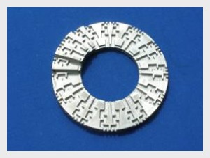
Example of a labyrinth cage